Tel: +86-20-3106 0625 Email: sales@motechmotor.com

Your location:Home >> SUPPORT >> Knowledge Base
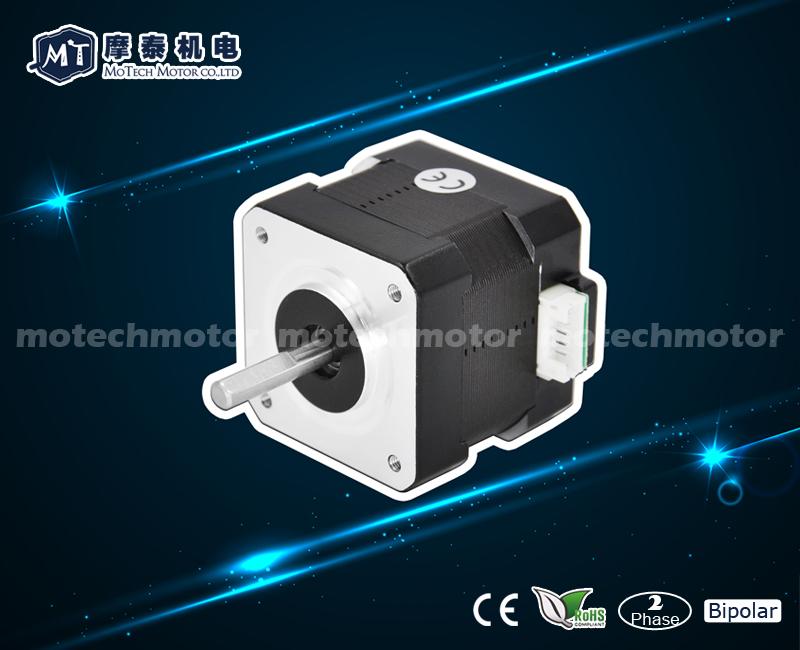
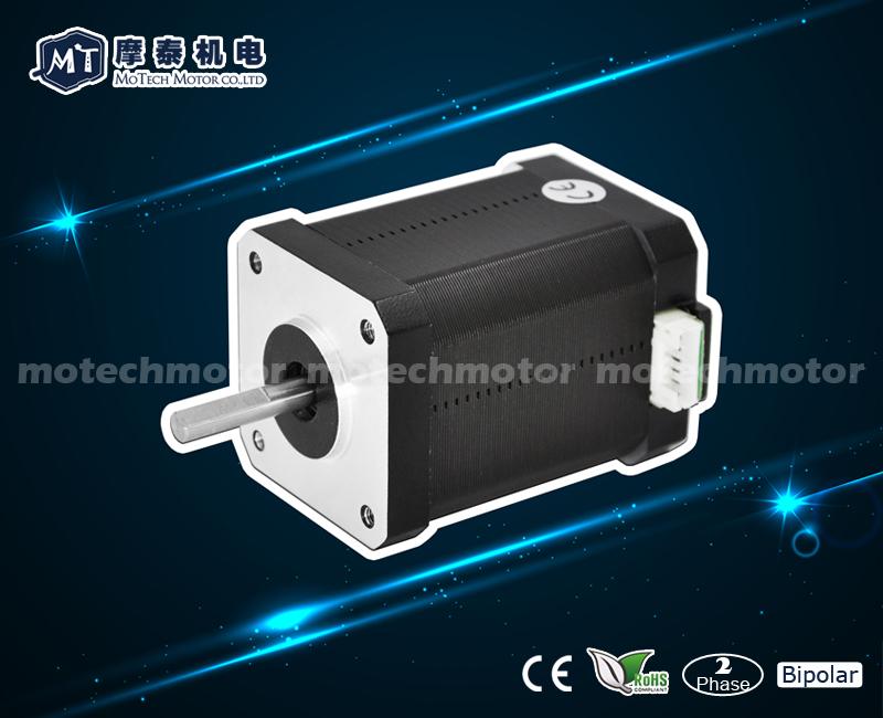
Knowledge BaseA stepper motor is a highly precise mechatronic actuator that converts electrical pulse signals into discrete angular displacements. The basic structure of a stepper motor is an intricate assembly composed of a stator, rotor, bearings, front and rear end covers, a center shaft, wave washers, and assembly screws.
Understanding the internal components and engineering functions of a stepper motor is crucial for selecting the right model, optimizing motion control performance, and ensuring system reliability.
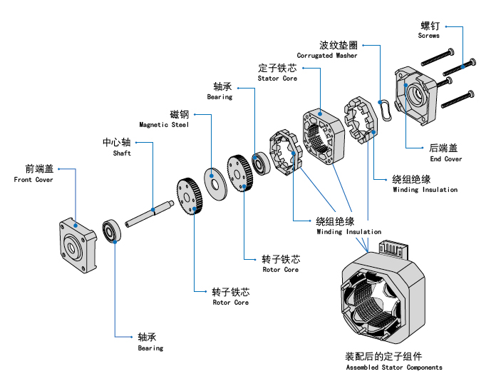
Stepper Motor Component & Function Matrix
For a quick engineering overview, the table below outlines the primary functions and industrial materials used in standard hybrid stepper motor construction:
|
Component Name |
Key Materials / Types |
Primary Function in Motion Control |
|
Stator Assembly |
Silicon steel laminations & copper wire
windings |
Generates a dynamic, rotating electromagnetic
field when energized by the driver. |
|
Rotor Core |
Permanent magnet sandwiched by multi-toothed iron caps |
Rotates in precise step angles (1.8 Degree or 0.9 Degree)
by aligning with the stator's magnetic teeth. |
|
Center Shaft |
High-strength stainless steel / Carbon steel |
Transmits the generated output torque and holding
torque to the external load. |
|
Precision Bearings |
Deep groove ball bearings (Front & Rear) |
Supports the rotating shaft, minimizes friction, and
ensures strict concentricity. |
|
End Covers (Flanges) |
Die-cast aluminum / Zinc alloy |
Securely houses the bearings, seals the motor cavity,
and defines the NEMA mounting interface. |
|
Wave Washers |
High-elastic spring steel |
Applies continuous axial preload to the bearings to
eliminate shaft endplay and dampen vibration. |
Detailed Analysis of Major Structural Components
1. The Stator (The Stationary Core)
The stator is the stationary part of the motor that establishes the foundational magnetic circuit. It consists of a laminated stator core made of high-permeability silicon steel to drastically minimize eddy current and hysteresis losses.
Insulated copper electromagnetic windings are tightly wound around the internal stator poles. When pulsed current from the stepper driver flows through these phase windings, it creates a localized magnetic field. The geometric precision of the stator poles directly determines the motor’s phase accuracy and holding torque capacity.
2. The Rotor & Center Shaft (The Rotating Assembly)
The rotor is the dynamic, rotating component suspended precisely inside the stator. In modern industrial automation, most applications utilize Hybrid Stepper Motors. The rotor features a strong permanent magnet encased between two multi-toothed iron caps.
3. Precision Ball Bearings
To maintain the microscopic air gap (often only tens of microns) between the stator and rotor teeth, high-quality front and rear ball bearings are non-negotiable.
4. Enclosure & Preload Components (End Covers, Wave Washers & Screws)
The mechanical stability of the motor depends heavily on its secondary structural elements:
The specialized mechanical construction of a stepper motor is engineered entirely to achieve reliable, open-loop incremental position control. By regulating external pulse frequencies and sequences, these motors deliver precise angular rotation without requiring expensive encoder feedback systems in standard applications. This cost-effective precision makes them irreplaceable in CNC machinery, 3D printing, medical automation, and sorting plotters.
For high-performance industrial applications, matching the structural parameters of a motor to your mechanical environment is key. If your project requires heavy-duty bearings, customized shaft flats/keyways, specialized NEMA flange mounting, or integrated IP-rated seals, MOTECH MOTOR delivers precision-engineered stepper motor solutions and comprehensive OEM customization. Contact our engineering support team for technical consulting and tailored specifications.


Scan QRCode
Follow Stepper Motors, Step-Servo Motors, Stepper Drivers News
 Tel: +86-20-31060625
 Fax: +86-20-31060635
 Email:sales@motechmotor.com
 Add.:Block 15th, Tian An Hi-tech Ecologocal Park, No.555, Panyu Avenue North, Panyu distrct, Guangzhou, China (511400)